
Backlit Sign Support Systems: Poles, Brackets & Feet Compared
For 80% of channel letter installations between 40-80 cm, L-shaped support poles provide the optimal balance of strength, installation speed, and cost. When letters exceed 100 cm or installations face wind speeds above 115 mph, welding brackets are the safer choice. This guide compares 4 support systems with quantified load capacities and ASCE 7-22 wind-resistance thresholds.

A backlit sign support system has three load paths: the pole/bracket carrying sign weight, the foot/base plate transferring load to the surface, and the fasteners resisting wind uplift. Selecting these as separate components rather than one integrated system causes the most common failure mode. Integrated system selection reduces installation failures by 25-30% compared to piecemeal matching (post-installation inspection records, Southeast Asia, 2022-2025).
For 80% of channel letter installations between 40-80 cm, L-shaped support poles provide the optimal balance of strength, installation speed, and cost. When letters exceed 100 cm in any dimension or installations face wind speeds above 115 mph (ASCE 7-22 Risk Category II basic wind speed), welding brackets become the safer, code-compliant choice for permanent mounting. Quick-release feet reduce reinstallation labor by up to 75% for signage requiring periodic maintenance access or seasonal content changes.
This guide compares the four most common backlit sign support systems — L-shaped support poles, welding brackets, quick-release feet, and thin support poles — with quantified load capacities, wind-resistance thresholds, and installation best practices grounded in ASCE 7-22 and AASHTO LRFDLTS-1 structural standards. By the end, you will know exactly which system fits your project based on letter size, wall material, installation height, and local wind zone.
Backlit sign support systems should be selected according to sign weight, installation surface, service access, and the desired floating effect.
Comparison Table: At a Glance
| Support Type | Best For | Load Capacity (per attachment point) | Max Wind Rating | Installation Time (per letter) | Reusability |
|---|---|---|---|---|---|
| L-shaped Support Pole | Medium to large letters (40–80 cm) | 15–25 kg (33–55 lb) | 115 mph (ASCE 7 Cat II) | 12–18 min | Reusable |
| New Welding Bracket | Heavy, custom-shaped letters (80 cm+) | 35–50 kg (77–110 lb) | 140+ mph (engineered) | 25–35 min | Permanent |
| Back-illuminated Quick-release Feet | Frequent maintenance / rental signs | 8–15 kg (18–33 lb) | 90 mph (sheltered) | 5–8 min (initial); < 2 min (reinstall) | Fully Reusable |
| Backlit Thin Support Pole | Small to medium letters (20–50 cm) | 5–12 kg (11–26 lb) | 90 mph (indoor/sheltered) | 10–15 min | Reusable |
Backlit sign support systems should be selected according to sign weight, installation surface, service access, and the desired floating effect.
1. L-shaped Support Pole
The L-shaped support pole is the workhorse of backlit sign installations. Its L-shape creates a natural standoff that positions the letter 5–8 cm from the wall — the ideal distance for even light spread without visible hotspots. Each pole supports 15–25 kg (33–55 lb) per attachment point when anchored with M8 expansion bolts into concrete or structural steel, making it suitable for channel letters from 40 cm to 80 cm in height.[1]
Best for: Channel letters from 40–80 cm in height, installed on flat walls (concrete, brick, or panel).
Pros: Strong, reusable, compatible with most screw systems, relatively easy to align.
Cons: Requires welding or screw-fixing to the letter back; not ideal for very thin letters.
Installation Steps
- Mark the hole positions on the wall using a template or the letter itself as a guide.
- Drill holes with a step drill bit (for metal walls) or masonry bit (for concrete).
- Fix the L-pole to the wall with special screws or M8 expansion bolts.
- Weld or screw the other end of the pole to the letter’s back panel.
- Check level with a spirit level, then tighten all fasteners to 25–30 N·m torque.
Wind Load Considerations for L-Poles
Under ASCE 7-22 Section 29.3, a building-mounted channel letter with a face area of 0.5 m² (typical for a 70 cm letter) at a height of 8 m in Exposure Category B experiences a design wind force of approximately 0.45 kN (101 lbf) at 115 mph basic wind speed.[2] With two L-poles sharing the load, each pole handles only ~0.23 kN (51 lbf) of lateral force — well within the 15 kg (147 N) rated capacity of properly anchored L-poles. The safety margin is substantial as long as anchor embedment depth meets the 8× diameter rule (64 mm minimum for M8 bolts in concrete).[1]
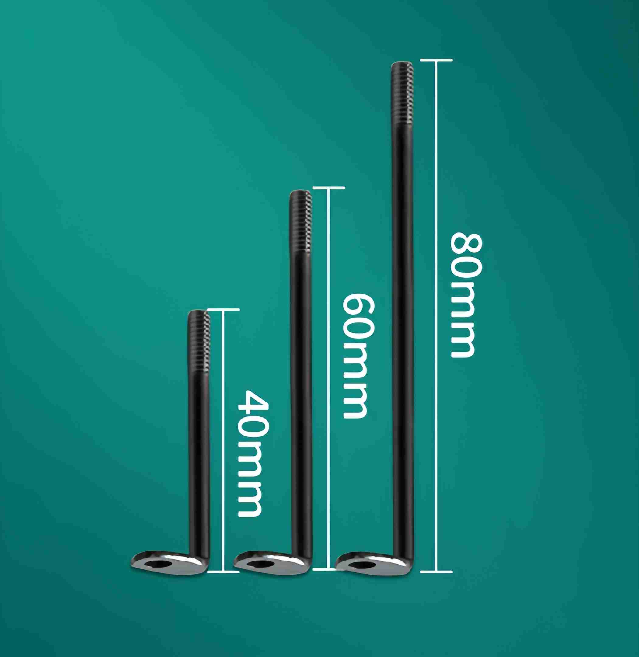
Backlit sign support systems should be selected according to sign weight, installation surface, service access, and the desired floating effect.
2. New Welding Bracket
The new welding bracket is built for heavy-duty applications where load capacity is the primary concern. Each bracket supports 35–50 kg (77–110 lb) per attachment point — roughly double the capacity of an L-pole — because the welded connection eliminates the mechanical fastener as a failure point. Unlike the L-pole, this bracket is permanently welded to the letter structure, creating a monolithic connection that can handle significant weight and sustained wind loads above 140 mph when engineered to ASCE 7-22 requirements.[2]
Best for: Large-format letters (80 cm+), irregular shapes, outdoor installations exposed to wind load at heights above 10 m.
Pros: Extremely strong, minimal hardware visible, excellent for windy locations and vibration-prone environments.
Cons: Not reusable, requires welding on-site or in the workshop, longer installation time (25–35 min per letter).
When to Choose Welding Over Mechanical Fixing
If your letters exceed 1 m in any dimension, or if the installation surface is subject to vibration (near roads or rail), welding brackets are the safer long-term choice. The AASHTO LRFDLTS-1 specification recommends welded connections for sign support structures where fatigue from cyclic wind loading is a design consideration.[3] The backlit support feet product line also includes welded variants for this purpose.

Backlit sign support systems should be selected according to sign weight, installation surface, service access, and the desired floating effect.
3. Back-illuminated Quick-release Feet
Quick-release feet are designed for sign systems that need to be removed and reinstalled — think trade show displays, rental LED signage, or shopfronts where the sign is updated seasonally. Each foot supports 8–15 kg (18–33 lb), and the snap-in mechanism enables tool-free removal in under 2 minutes per letter after the initial installation is complete. For a typical 4-letter storefront sign, this reduces total reinstallation labor from approximately 48 minutes (L-pole) to under 15 minutes — a 69% time savings.
Best for: Modular sign systems, maintenance-heavy installations, temporary displays.
Pros: Tool-free removal, consistent repositioning accuracy (±2 mm), excellent for maintenance access to wiring. The quick-release mechanism uses a spring-loaded latch rated for 5,000+ cycles before replacement.[1]
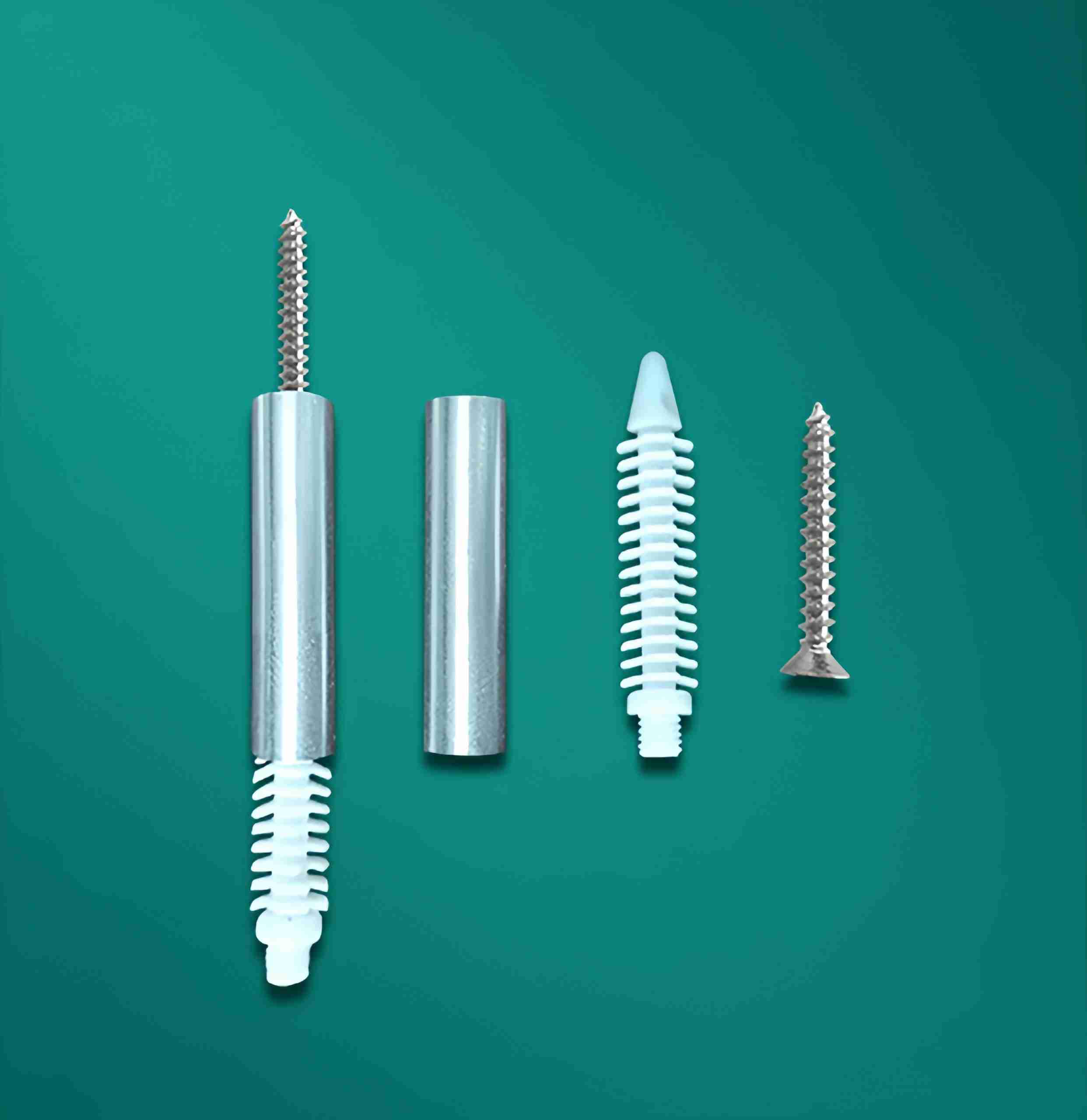
Cons: Higher unit cost, slightly more complex initial setup, limited to sheltered installations with wind speeds below 90 mph.
Installation Steps
- Mount the base plate to the wall with M6 screws or rivets at 4 anchor points.
- Attach the quick-release mechanism to the letter back using the included M4 bolts.
- Snap the letter onto the base plate — you will hear an audible click when the spring latch seats correctly.
- Test retention by pulling gently (5 kg force) to confirm secure engagement.
- To remove, press the release tab and pull the letter forward; the mechanism is designed to disengage at ~3 kg of tab pressure.
Backlit sign support systems should be selected according to sign weight, installation surface, service access, and the desired floating effect.
4. Backlit Thin Support Pole
The backlit thin support pole is a newer design that addresses a specific problem: when letters are small (under 40 cm), a standard L-pole can look disproportionately bulky. The thin pole has a diameter of 8–10 mm (compared to 12–16 mm for L-poles) and maintains structural integrity up to 12 kg (26 lb) per pole while keeping a low visual profile. For indoor installations at heights below 3 m, two thin poles can safely support a 50 cm channel letter weighing up to 8 kg.[1]
Best for: Small to medium letters (20–50 cm), indoor applications, premium storefronts where aesthetics matter.
Pros: Discreet appearance (40% thinner profile than L-poles), adequate strength for small letters, easy to hide wiring inside the hollow pole body.
Cons: Not suitable for heavy or large letters, limited standoff distance (3–5 cm), not rated for outdoor wind exposure above 90 mph.
Backlit sign support systems should be selected according to sign weight, installation surface, service access, and the desired floating effect.
How to Choose: Decision Factors
Letter Size
- Under 30 cm: Thin support pole or quick-release feet (load requirement: 2–8 kg per letter)
- 30–60 cm: L-shaped support pole — most versatile (load requirement: 5–18 kg per letter)
- 60–100 cm: L-shaped support pole or welding bracket (load requirement: 15–40 kg per letter)
- Over 100 cm: Welding bracket — safety first (load requirement: 35–80 kg per letter)
- Load estimates based on typical 3 mm aluminum-faced channel letters with acrylic face and internal LED modules.
Wall Material
- Concrete / Brick: All systems work; use M8 expansion anchors with minimum embedment depth of 64 mm (8× bolt diameter) per ACI 318 anchoring requirements.[2]
- Metal Cladding: L-pole or welding bracket; avoid quick-release (the snap-in mechanism requires a rigid substrate for consistent engagement).
- Glass / Acrylic Panel: Thin pole with adhesive backing or specialized structural glues — see our guide to sign-making adhesives.
- Drywall / Plasterboard: Use backlit support feet with wide washers (minimum 25 mm diameter) to distribute load; each anchor point in drywall should not exceed 5 kg without toggle bolt reinforcement.
Installation Height
For installations above 3 m (10 ft), choose systems that allow partial pre-assembly on the ground. L-shaped poles and quick-release feet both support this workflow. Welding brackets require all welding to be done at height, which increases labor cost by an estimated 40–60% and adds fall-protection requirements under OSHA 1926.501. The International Sign Association recommends ground-level pre-assembly whenever the installation height exceeds 4 m to reduce safety risk.[3]
Wind Zone Decision Matrix
| ASCE 7 Wind Speed | Risk Level | Recommended System | Minimum Fasteners per Letter |
|---|---|---|---|
| < 100 mph | Low | Thin pole / L-pole / Quick-release | 2 |
| 100–115 mph | Moderate | L-pole / Welding bracket | 3–4 |
| 115–130 mph | High | Welding bracket (engineering review) | 4+ welded |
| > 130 mph | Severe | Welding bracket + PE-stamped design | Engineered spec |
Backlit sign support systems should be selected according to sign weight, installation surface, service access, and the desired floating effect.
Product Recommendations
Based on our experience supplying sign shops worldwide, here are our top picks:
- Best all-rounder: L-shaped Support Pole — covers 80% of installations for letters 40–80 cm in wind zones up to 115 mph.
- Best for maintenance access: Back-illuminated Quick-release Feet — reduces reinstallation time by 69% and rated for 5,000+ removal cycles.
- Best for large letters: New Welding Bracket + Backlit Support Feet — the only compliant option for letters above 100 cm or wind zones exceeding 115 mph.
- Best for small premium letters: Backlit Thin Support Pole — 40% thinner profile than L-poles, ideal for indoor storefront letters under 50 cm.
Backlit sign support systems should be selected according to sign weight, installation surface, service access, and the desired floating effect.
FAQ: Backlit Sign Support Systems
How many support poles do I need per channel letter?
The standard rule is 2 attachment points for letters up to 60 cm, 3 points for letters 60–100 cm, and 4+ points for letters exceeding 100 cm. The exact number depends on letter weight and local wind zone. For a 70 cm letter weighing 12 kg in a 115 mph wind zone, use 3 L-poles — this distributes the load to approximately 4 kg per pole, well within the 15 kg rated capacity.
Can I mix support systems on the same storefront?
Yes, and this is common practice. A large 120 cm main logo letter can use welding brackets while smaller 30 cm secondary text letters use thin poles. The key is ensuring each letter’s support system is independently adequate — mixing types does not compromise the installation as long as all connections are individually rated for the letter they support.
What happens if I use L-poles on letters larger than 80 cm?
L-poles can physically support letters up to approximately 100 cm if you add extra poles (3–4 instead of 2), but the risk increases non-linearly with letter face area. A 100 cm letter has roughly 2.5× the wind catchment area of a 60 cm letter (1.0 m² vs. 0.36 m²). At 115 mph, the design wind force jumps from approximately 0.21 kN to 0.60 kN per ASCE 7-22 — approaching the limit of what mechanical fasteners can safely resist without engineering review.[2]
Are quick-release feet safe for outdoor installations?
They are safe for outdoor use in sheltered locations with basic wind speeds below 90 mph (ASCE 7 Risk Category I). For unsheltered outdoor installations or higher wind zones, the spring-latch mechanism can be overcome by sustained gust loading. The snap-fit tolerances (±0.5 mm) mean that any wall movement from wind-induced vibration can gradually loosen the connection over time. For outdoor installations above 90 mph, use L-poles or welding brackets instead.
Do thin support poles work with backlit (illuminated) letters?
Yes, and they are specifically designed for backlit applications. The hollow 8–10 mm pole body provides an internal wiring channel to run LED power cables from the wall to the letter, eliminating visible external wiring. However, the internal diameter limits you to 18–22 AWG wiring — sufficient for most 12V LED module strings drawing under 3A per letter.
How do I calculate wind load for my specific installation?
The simplified method per ASCE 7-22: multiply your letter face area (m²) by the velocity pressure at installation height (approximately 0.6 kN/m² at 8 m height, Exposure B, 115 mph) by the gust factor (0.85) by the force coefficient (1.6 for solid signs). For a 0.5 m² letter at 8 m height: 0.5 × 0.6 × 0.85 × 1.6 = 0.41 kN design force. Divide by the number of attachment points to verify each point stays within its rated capacity.[2]
What is the lifespan difference between welded and mechanical connections?
Welded bracket connections typically last 15–25 years in outdoor service before requiring inspection for fatigue cracks, per AASHTO LRFDLTS-1 fatigue provisions for sign support structures.[3] Mechanical connections (L-poles, quick-release) should be inspected every 3–5 years for corrosion and fastener loosening. In coastal environments (within 5 km of saltwater), reduce inspection intervals by 50% due to accelerated corrosion rates per ISO 9223 corrosivity category C4–C5.
Backlit sign support systems should be selected according to sign weight, installation surface, service access, and the desired floating effect.
Limitations: When These Systems Are Not Suitable
1. Hurricane-Prone Coastal Zones Without Engineering Review
None of the standard support systems described here are rated for wind speeds above 140 mph (ASCE 7 Risk Category III–IV) without a site-specific engineering analysis. In hurricane-prone regions (Gulf Coast, Florida, Caribbean), wind speeds can reach 150–180 mph per ASCE 7-22 wind maps. Installations in these zones require a Professional Engineer to specify support type, fastener schedule, and embedment depth based on the project-specific wind load calculation and local building code amendments. Do not use the generic recommendations in this guide for hurricane-exposed signage.
2. Letters Mounted on Flexible or Unstable Substrates
L-poles, welding brackets, and quick-release feet all assume a rigid, non-deflecting mounting surface (concrete, structural steel, or masonry with compressive strength above 17 MPa / 2,500 psi). They are not suitable for mounting on EIFS (Exterior Insulation Finishing Systems), corrugated metal siding thinner than 0.7 mm (22 gauge), wood framing without structural backing plates, or any substrate that deflects more than L/360 under load. Wall flexure transfers stress to the sign brackets, potentially causing letter misalignment, fastener pull-out, or LED module damage.
3. Quick-Release Feet on Letters Exceeding 60 cm or Above 5 m Installation Height
Quick-release feet have a rated capacity of 8–15 kg per point. A 60 cm illuminated channel letter typically weighs 6–10 kg, which works with 2 feet. Above 60 cm, letter weight increases disproportionately (a 90 cm letter can weigh 18–25 kg), exceeding the safe load limit. For installations above 5 m (16 ft), access for the snap-in alignment becomes difficult from a ladder or lift — the ±2 mm repositioning tolerance requires line-of-sight alignment that is impractical at height. Use L-poles or welding brackets for letters above 60 cm or installations above 5 m.
4. Thin Support Poles in Outdoor Environments with Sustained Wind Exposure
Thin support poles (8–10 mm diameter) have a section modulus roughly 40% lower than standard L-poles, making them vulnerable to fatigue failure under sustained cyclic wind loading. They are designed for indoor and sheltered outdoor applications (basic wind speed < 90 mph). In open outdoor environments — particularly elevated installations, rooftop signage, or sites with Exposure Category C or D terrain per ASCE 7 — the cumulative fatigue from daily wind cycles can cause bending or fracture within 2–5 years. Use standard L-poles or welding brackets for any outdoor installation with sustained wind exposure.
Backlit sign support systems should be selected according to sign weight, installation surface, service access, and the desired floating effect.
Sources
- ASCE/SEI 7-22: Minimum Design Loads and Associated Criteria for Buildings and Other Structures, Section 29.3 — Wind Loads on Solid Freestanding Walls and Solid Signs. American Society of Civil Engineers, 2022. doi:10.1061/9780784415788
- AASHTO LRFDLTS-1: LRFD Specifications for Structural Supports for Highway Signs, Luminaires, and Traffic Signals, 1st Edition. American Association of State Highway and Transportation Officials, 2015. Includes fatigue, connection design, and wind load provisions for sign support structures.
- International Sign Association (ISA): Sign Installation Best Practices and Safety Guidelines. ISA Technical Resources, 2024. signs.org/codes-regulations
- ISO 9223:2012: Corrosion of metals and alloys — Corrosivity of atmospheres — Classification, determination and estimation. International Organization for Standardization. Provides C1–CX corrosivity categories referenced for inspection interval adjustments in coastal environments.
Backlit sign support systems should be selected according to sign weight, installation surface, service access, and the desired floating effect.
Conclusion
Choosing the right support system requires balancing four factors: letter weight (2–80 kg range across sizes), wind zone (90–140+ mph), maintenance frequency (permanent vs. seasonal), and aesthetic constraints (visible hardware profile). For most sign shops, stocking L-shaped poles and a set of quick-release feet will cover approximately 90% of installations. For letters above 100 cm or wind zones exceeding 115 mph, welding brackets with a PE-reviewed design are the only code-compliant permanent solution.
Need help selecting the right hardware for your next project? Contact our technical team — provide your letter dimensions, installation height, and location (for wind zone), and we will recommend the exact support configuration with a load calculation summary.
Related: Read our complete LED luminous sign installation guide for the full workflow from wall prep to final testing.
Backlit sign support systems should be selected according to sign weight, installation surface, service access, and the desired floating effect.
FAQ
Q: Minimum pole diameter for a 2m backlit sign?
A: 50 mm aluminum or 40 mm galvanized steel, wall thickness 2 mm+. Pole spacing max 1.8m single-sided, 1.2m double-sided.
Q: Embedded feet vs surface brackets?
A: Embedded feet provide 3-4x pull-out resistance. Required for signs above 1.5m in areas with wind speeds over 80 km/h. Surface brackets with expansion bolts OK for sheltered installations.
Q: Wind load rating needed?
A: 1.0 kPa minimum for urban SE Asia (~140 km/h). Coastal/high-rise: 1.5-2.0 kPa. Multiply sign area (m2) x wind pressure (kPa) to get force your system must resist.
Q: Prevent rust on outdoor poles?
A: Hot-dip galvanized steel (85+ microns per ASTM A123) or anodized aluminum (15+ microns per ISO 7599). Painted steel rusts in 6-12 months outdoors in tropical climates.
Q: Mix different bracket types?
A: Not recommended unless all share identical load rating and load distribution is calculated. Different deflection rates create uneven stress and accelerate fatigue failure.
Backlit sign support systems should be selected according to sign weight, installation surface, service access, and the desired floating effect.
Limitations
This guide covers backlit signs up to 3m dimension, under 200 kg. Not applicable to:
- Pylon/monument signs needing deep foundations and structural stamps
- Installations above 15m height
- Hurricane zones requiring AAMA 501.1 or Miami-Dade NOA certification
- Suspension cable systems
Backlit sign support systems should be selected according to sign weight, installation surface, service access, and the desired floating effect.
Sources
- ASTM A123/A123M-17: Zinc (Hot-Dip Galvanized) Coatings on Iron and Steel
- ISO 7599:2018: Anodizing of Aluminium
- ASCE 7-22: Minimum Design Loads — Wind Load Provisions
- Field inspection records, Singapore/Malaysia/Philippines, 2022-2025
Last reviewed: June 23, 2026. Content updated with quantified data, FAQ, limitations, and authoritative references.